11.1 Overview

Figure 1.
A number of sensors (B) are connected to a box (A). The example above shows the 400 model. For larger models, this is divided into a left and a right box. See the following example.

Figure 2.
Detectors supplied for the combi machines appear in brackets in the table below.
|
Machine |
Number of detectors (seed) |
Number of SeedEye boxes |
|
RDA 400S |
32 |
1 |
|
RDA 600S |
48 |
1 |
|
RDA 800S |
64 |
2 |
|
RDA 600C |
48 (24 |
1 (1) |
|
RDA 600J |
48 |
1 |
|
RDA 800C |
64 (32) |
2 (1) |
|
RDA 800J |
64 |
2 |
Each sensor has an LED light. The meanings of the different colours are shown below.

Figure 3.
|
Colour |
|
|
Orange |
Waiting for registration |
|
Green |
Registered, in operation |
|
Red |
Voltage too low |
|
Orange pulsating slowly |
Dusty |
|
Red pulsating quickly |
Blocked |
|
Blue pulsating |
Updating software Testing communication with the sensors |
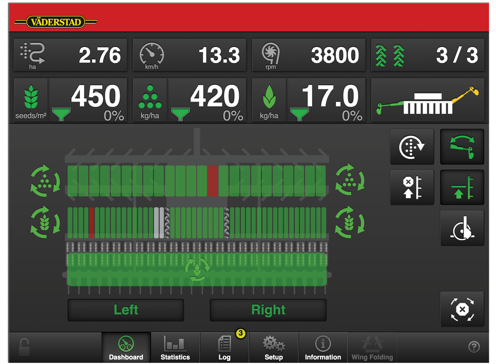
Figure 4. Monitoring on the home screen