6.3.2 Calculated tramline
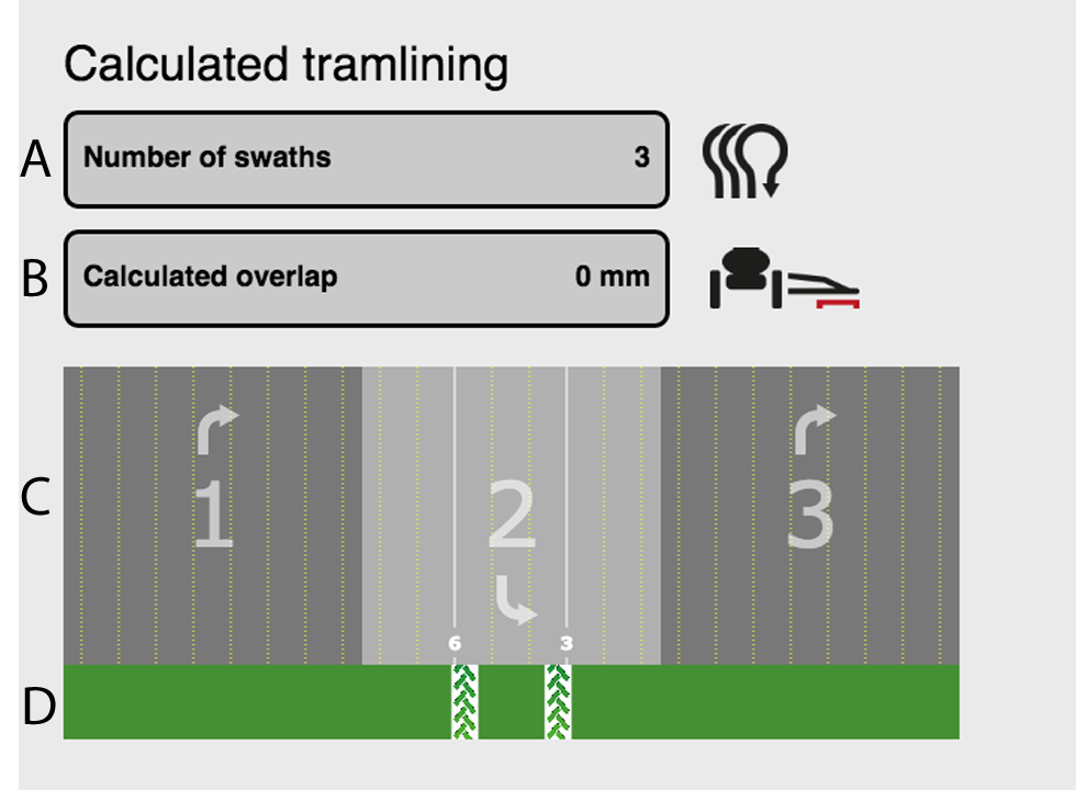
Figure 1.
Total number of bouts in the tramline program
Overlap for the spraying implement
Bouts for the drill
Bouts for the spraying implement
The yellow dotted lines (C) display the row units that sow and the white solid lines display the row units that will be shut off due to the tramlining.
The example in the above illustration displays that row units 3 and 6 will be shutdown because of the tramline in bout number 2 in the tramline program.
You can scroll left and right in order to see the entire calculated sequence.
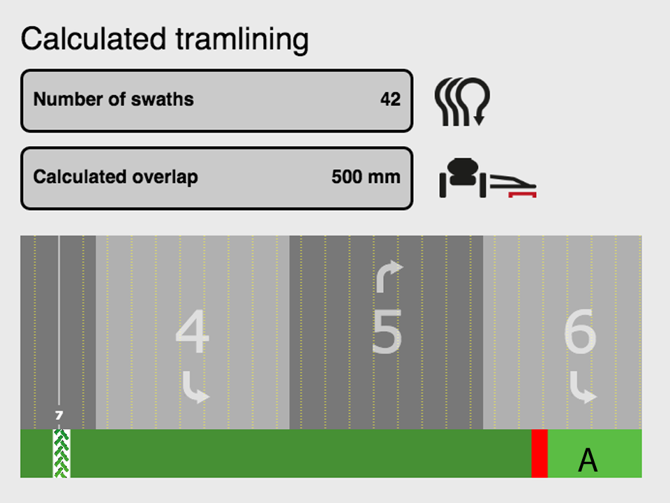
Figure 2.
Indicates the overlap made by the spraying implement between each bout.
The overlap occurs if the working widths of the drill and the spraying implement do not run equally.